Probably took me about four hours ;-D So much checking and measuring.
Probably took me about four hours ;-D So much checking and measuring.
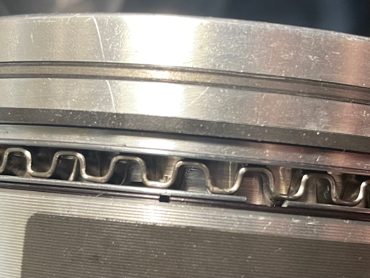
I know, I’m slow… Fitted rings on first piston. I then realised I probably need to gap the oil support rail. Struggling to find information, ideas welcome.
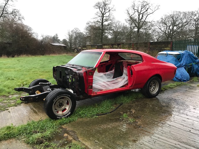
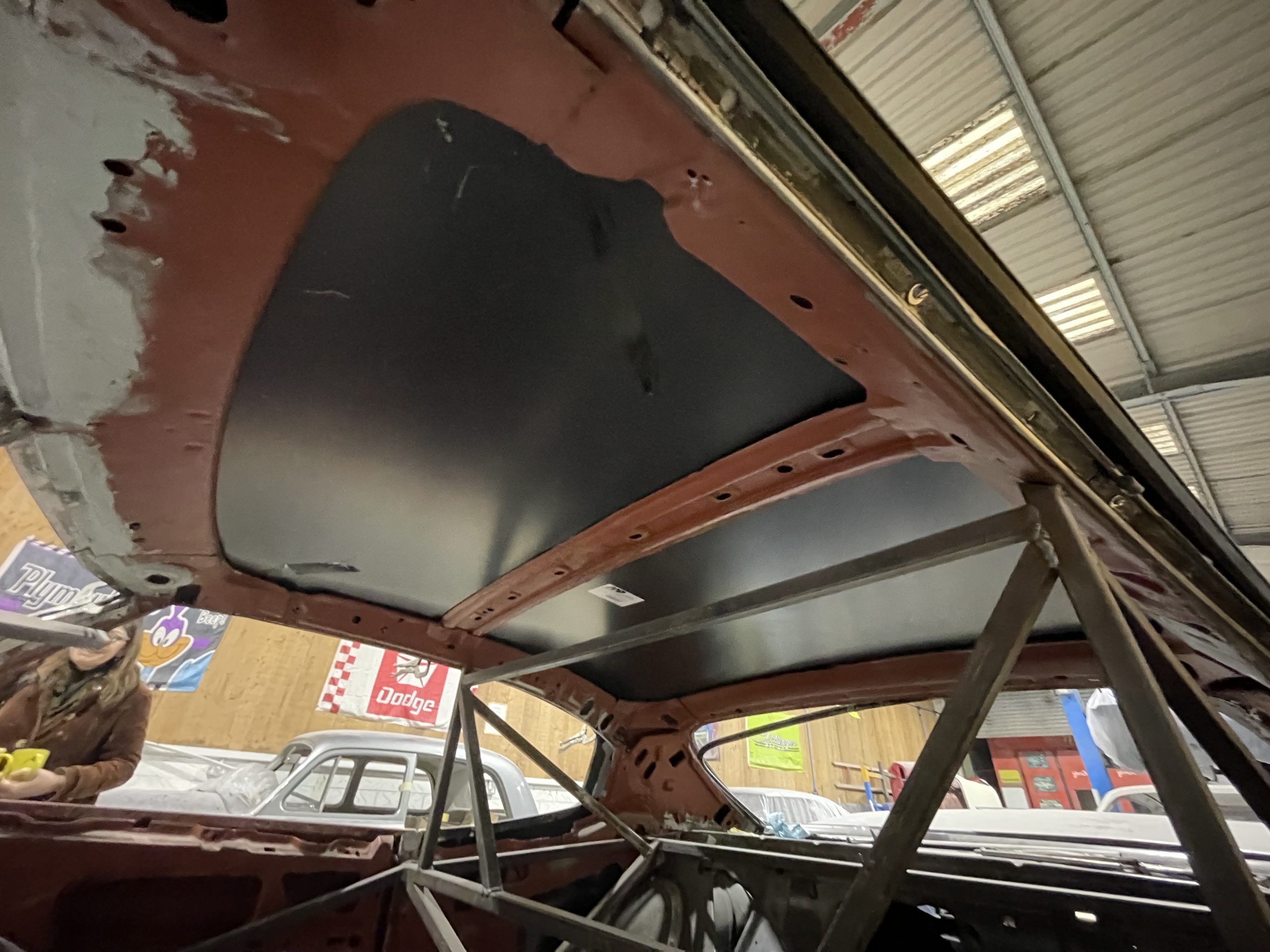
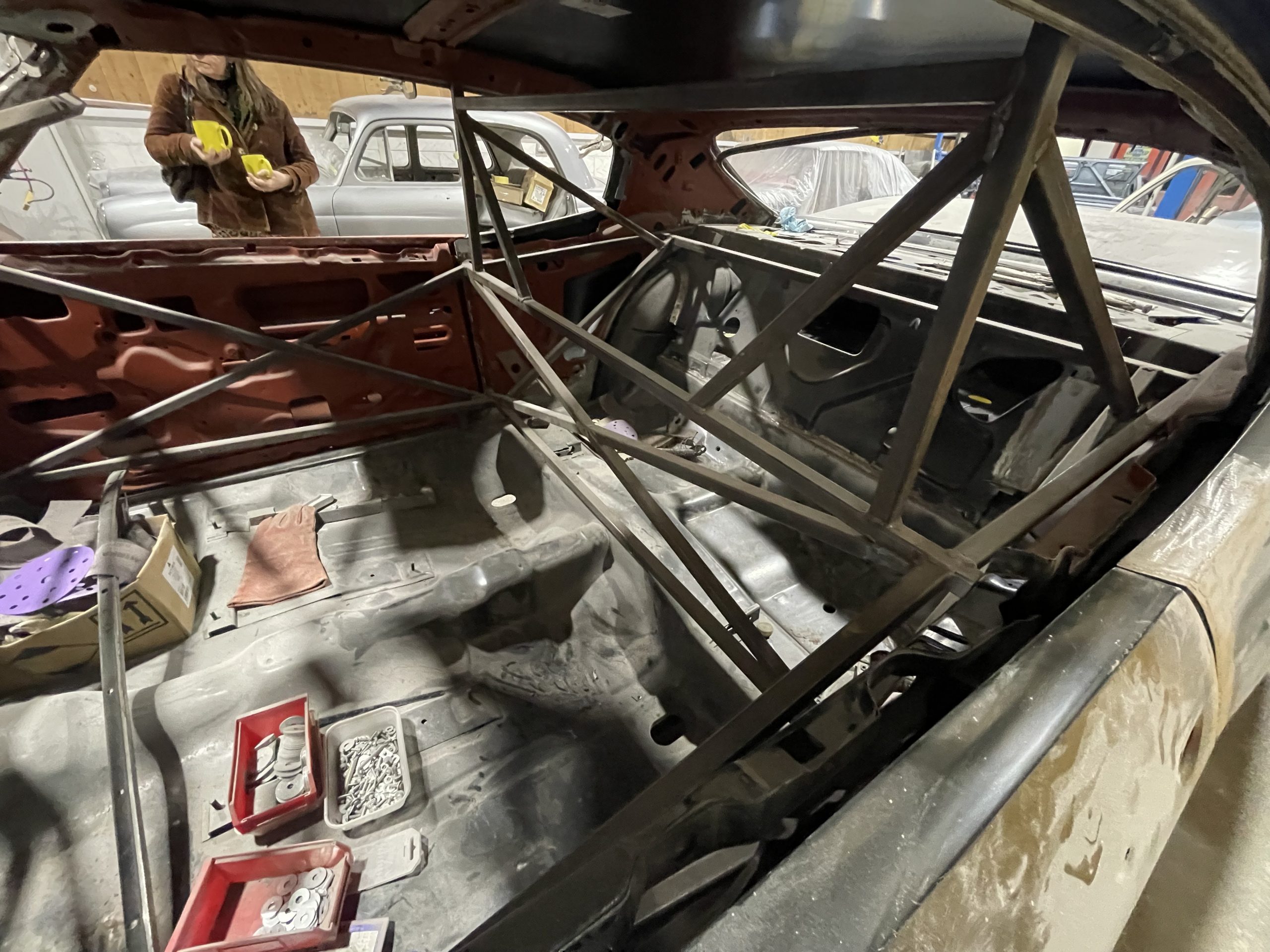
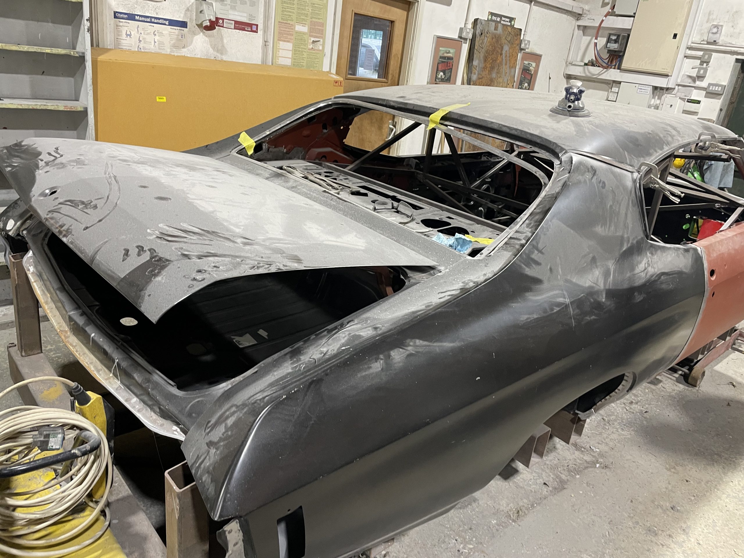
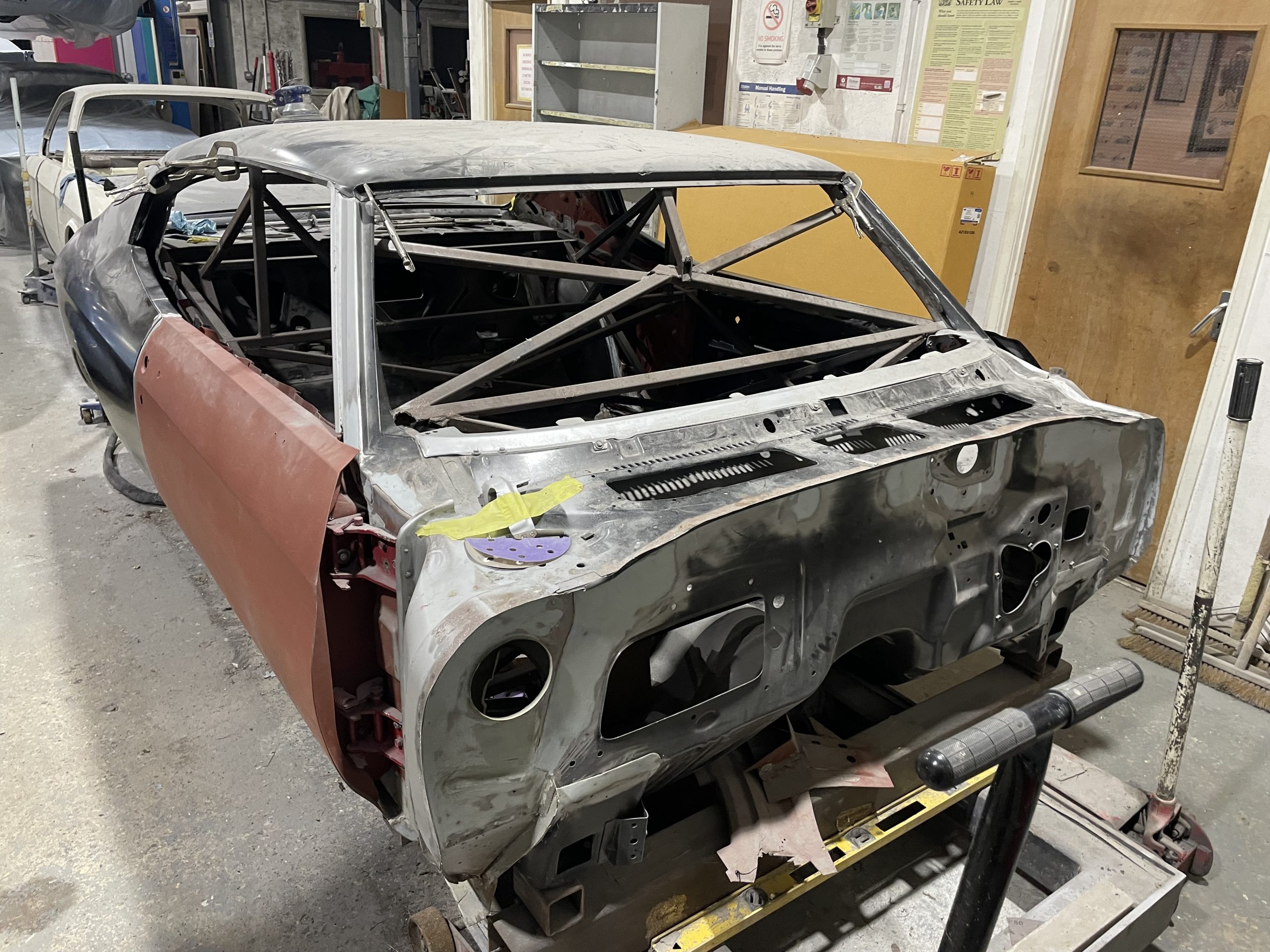
We had one of those rare days yesterday, of visiting Big Green. Will still be a year until we have it back, sadly. Mainly the roof and some cosmetic things to complete, then painting.
I’m not an expert, definitely don’t use this as a guide 🙂
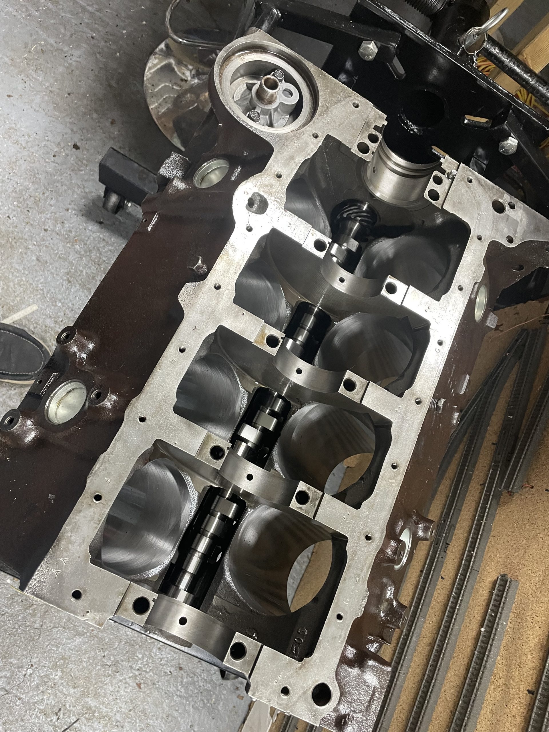
Block with cam fitted.
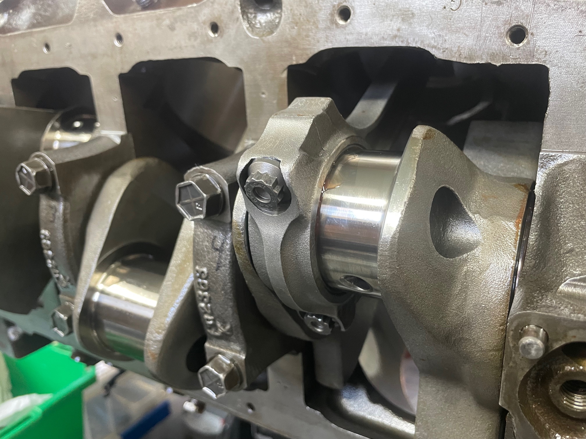
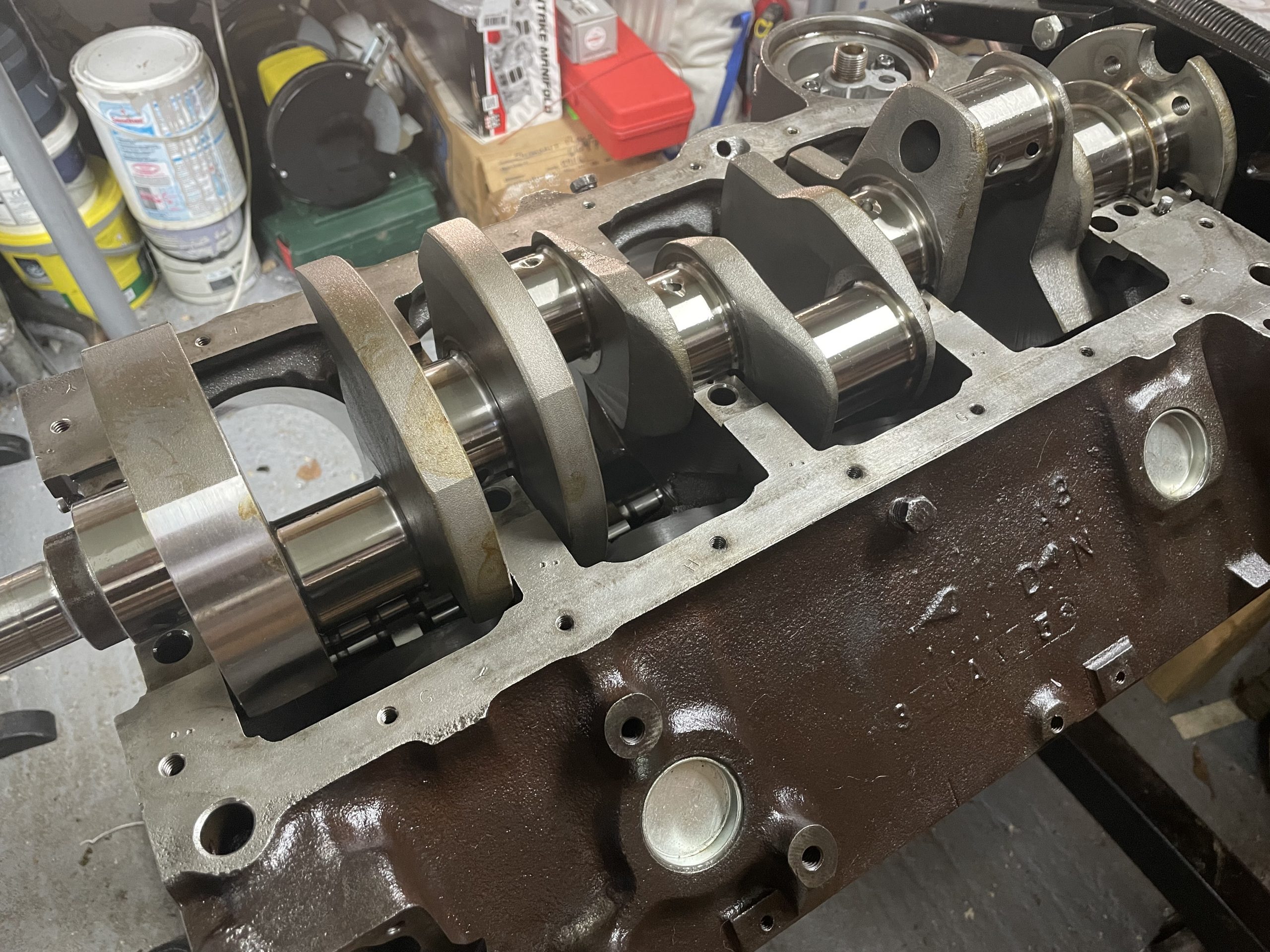
Crank fitted.
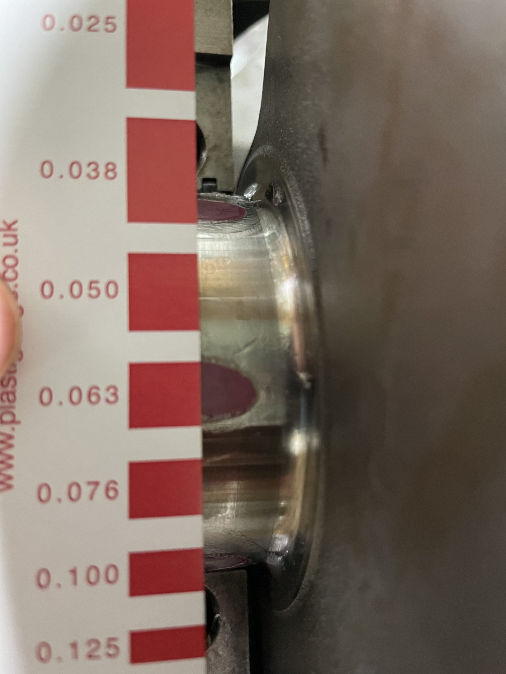
Measuring bearing clearance using Plastigage.
Measuring end-float.
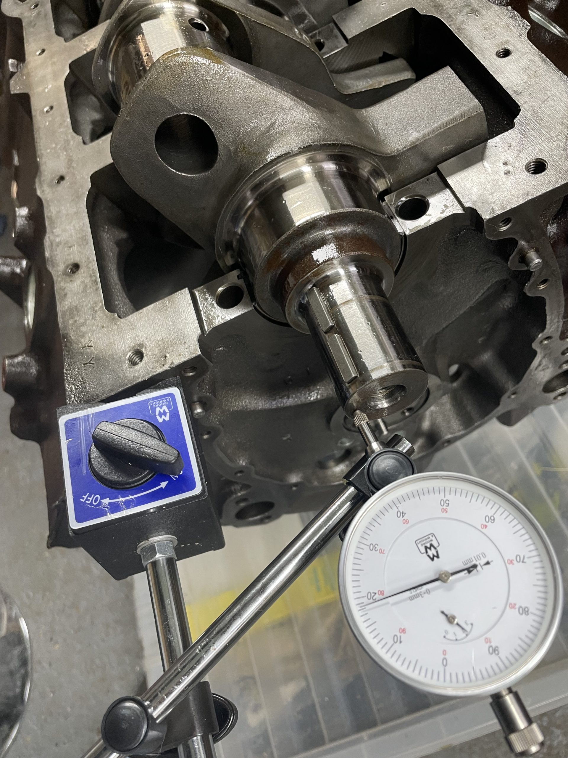
Everything I measured up until this point was within spec. The end-float did drop from 0.0055″ to 0.0028″ when I tightened the thrust bearing but I did shove the crank backwards and forwards before tightening and was told this is normal.
Test spin
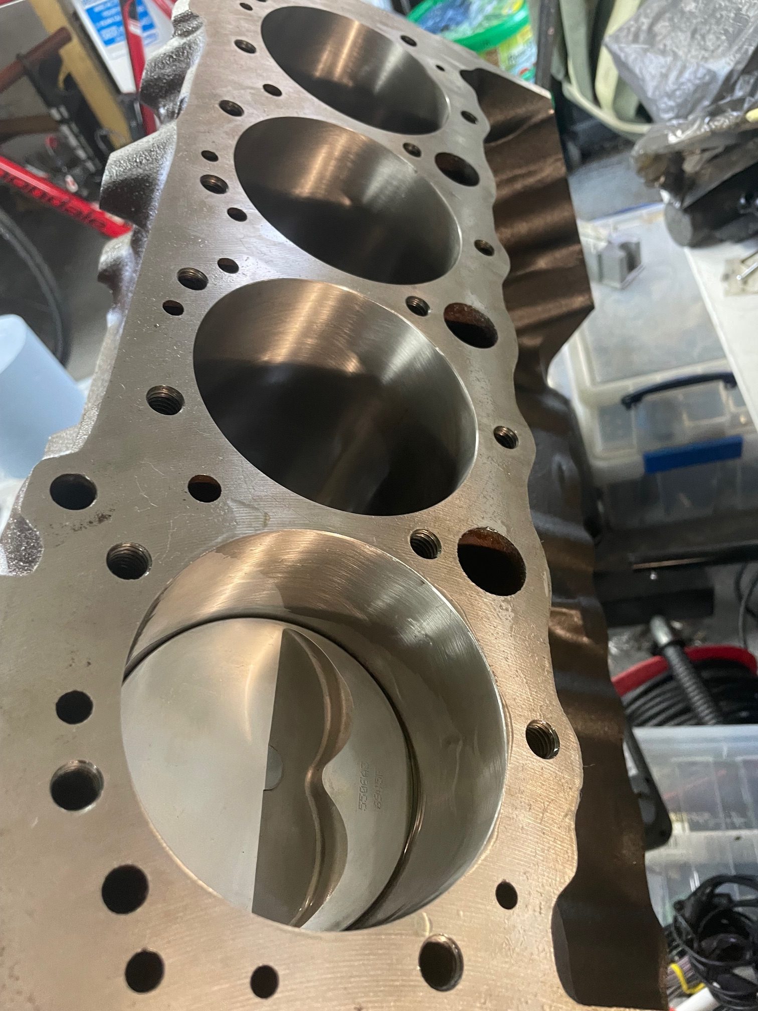
This company is plain dangerous. After starting to build this engine, I measured the piston to cylinder clearance, which, according to the piston specification sheet (that MJA was handed) should be 0.0035″. The cylinders MJA bored are somewhere between 0.0045-0.0055″, not even consistent.
They also filed the piston rings. Moly rings where the top ring is meant to have a gap of 0.018″ and the second ring 0.020″. Some of them, both top and second, are as low at 0.016″. Thank god I measured them.
MJA is just plain dangerous. How can no-one have picked up on this before?
I might be able to salvage this by having the piston skirts coated but it is even more money MJA has cost me.
I have had the mis-fortune of dropping off an engine block for re-manufacturing at MJA Engineering in Broomgrove and want to warn other against this company as they really don’t know what they’re doing. I think it’s a case of “Don’t attribute to malice what is adequately explained by stupidity”.
I dropped off an SBC block at MJA Engineering to have it re-manufactured and bored over to become an 383 stroker. All seemed fine, they were friendly and appeared knowledgeable, no alarm bells ringing at this point. I picked the block up again, £940 lighter.
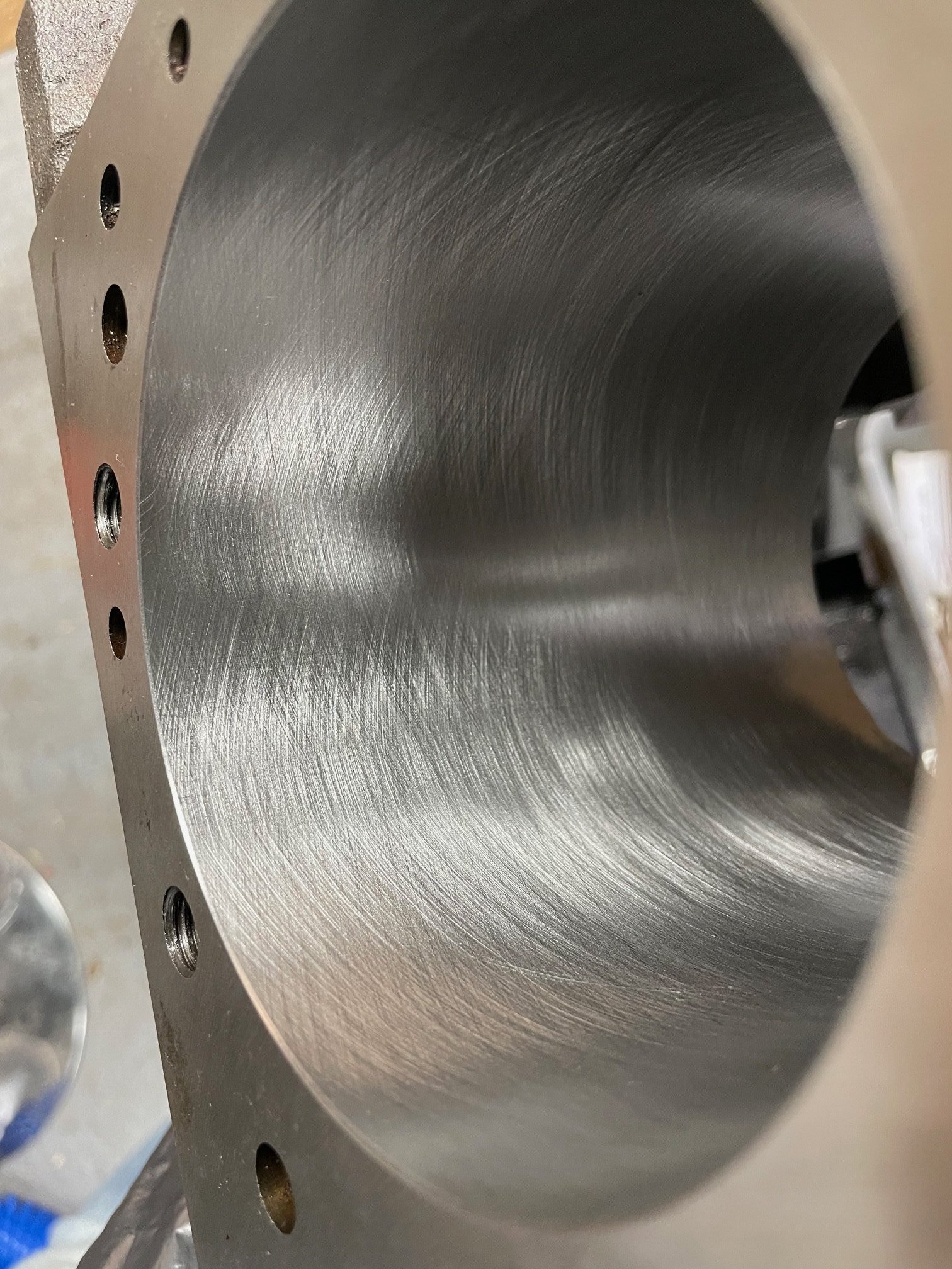
Upon inspection in my workshop, I noticed a scratch in one of the bores. It was black and you could feel it with your nail. You could also clearly feel the hone pattern with your fingers. Not being an expert, I posted the photo of the scratch on a forum. And yes, I know people on fora are not necessarily experts either, but feedback and discussion can still be helpful.
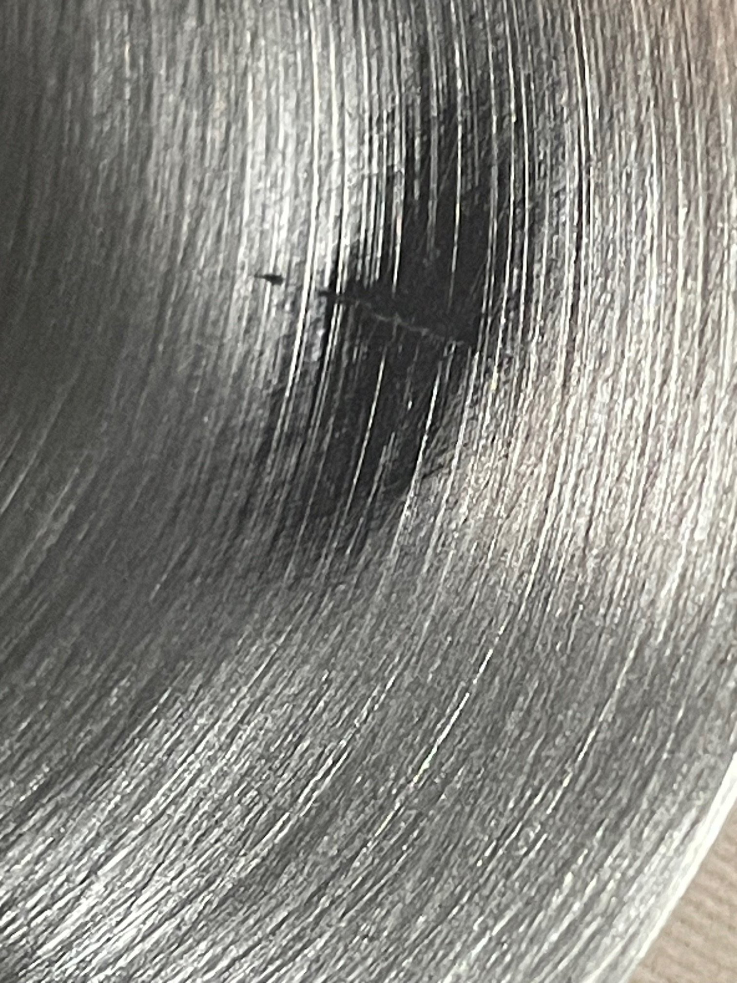
Everyone on the forum was in agreement though, and I even started PMing with a machinist about the honing. It was absolutely too rough for modern rings. MJA had used a grit (150) that was only fitting back in the days of steel rings.
I contacted MJA about this and they told me that:
(They later admitted they did not have any stones above 150 grit and they don’t even appear to have a plateauing stone)
I obviously could not continue this build with 20 people (including two machinists) telling me this was badly wrong. I took it to another engine remanufacturing company who were quite shocked at MJA’s workmanship. They agreed to take on the block and sleeved the damaged cylinder and plateau-honed all the cylinders to a much better finish.
MJA’s work was just shockingly bad and ignorant. To make matters worse, their business card had the FER mark on it (Federation of Engine Re-Manufacturers) but when I contacted FER to complain, they said MJA were no longer a member. I queried the reason for this with MJA Engineering but they did not answer this question, so I can only assume they were expelled.
In short, don’t use MJA engineering in Broomsgrove, even if they were on TV. It doesn’t make them experts (clearly).
After seeing a ready made garage pit at the NEC 20 years ago, I have been thinking about getting a pit or two-post lift. It always seemed too complicated, too expensive, just too much…
I started following “Seaside Garage” on Youtube, who described the difference his mid-rise scissor had made. It’s not a full height lift, but cheaper and much more convenient! I started looking around and found Strongman and their apparently popular “Clifton” lift (previously “Montford”?).
Link to Seaside Garage: Seaside Garage – YouTube
It wasn’t the cheapest lift, but fitted the bill perfectly. Delivered within two days, and despite weighing 500Kg, I set it up myself. Here it is in situ (yes, I fitted the ramps to the wrong sides, handles need to be on the outside):
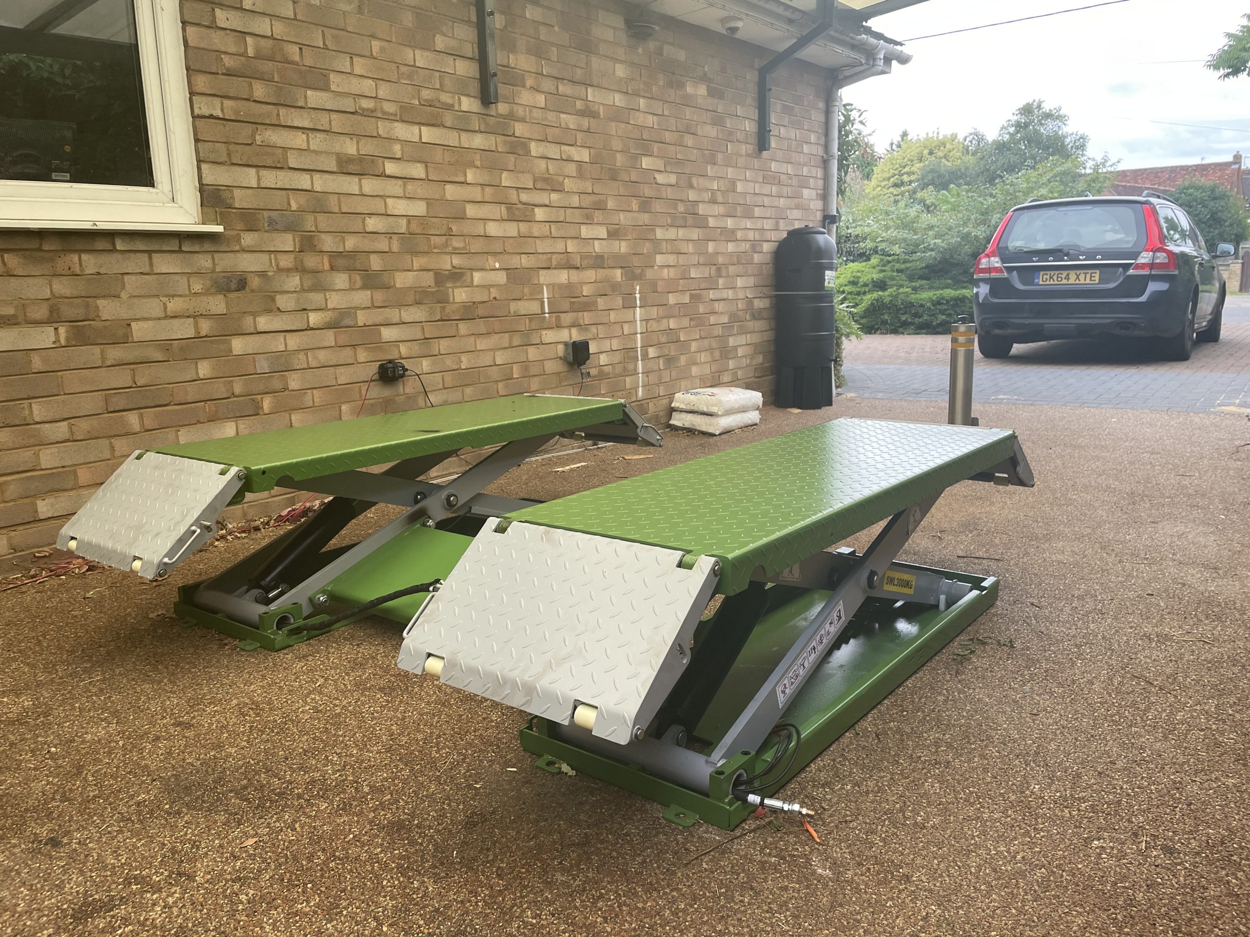
Still not hooked up to the “Control Tower” and it needs a commando socket installed. Will post a video of the first test run. (EDIT: Now posted below)
The red lamp on the Control Tower, and the manual does not mention this at all, is not a fault indicator as I first thought. It is a warning to everyone in the shop (and my neighbours) that the lift is lowering, and it is LOUD! So loud that I put some Duck tape over it, which brought it down to a more pleasant sound level.

I swapped the control tower connection side to be by the wall, which, TBH, I don’t think it was really designed for. The only slight issue is that the cable bracket for the stop switch has no holes to be screwed into on the other side. Double-sided tape should hold it in place.
The Chinese Google-translated manual is awful. Poor quality photos, lack of information, and written in bad English. The hydraulic line joins were not tightened from the factory, so oil leaked everywhere the first time I ran it. The dip-stick for the oil reservoir is also shiny metal, so useless. I will try to mark min and max with permanent marker on the reservoir itself.
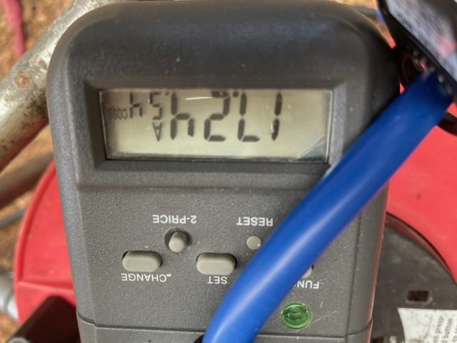
The motor is a 3HP motor and uses 18A at cos φ .54 as seen below.
(Or how to get Volvo D4 cambelt on)
I just quickly wanted to share an easier way of slipping the cambelt over the last pulley to what VIDA or Youtube suggests. I did this on a Volvo VEA D4 D4204T5 2.0 diesel engine in a V70 from 2014.
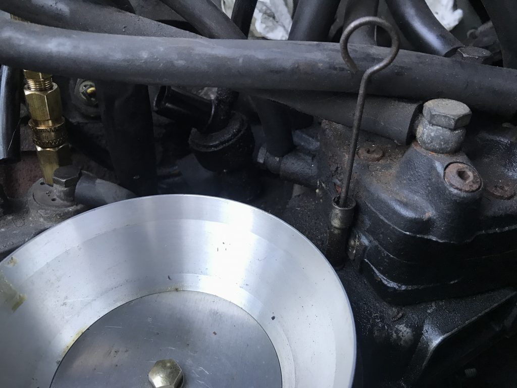
VIDA says to pull the belt over the cam pulley last, but it’s not very easy. Instead, feed the belt up on both sides as tightly as you can and leave the belt running across the top idler (pointed to in the photo).
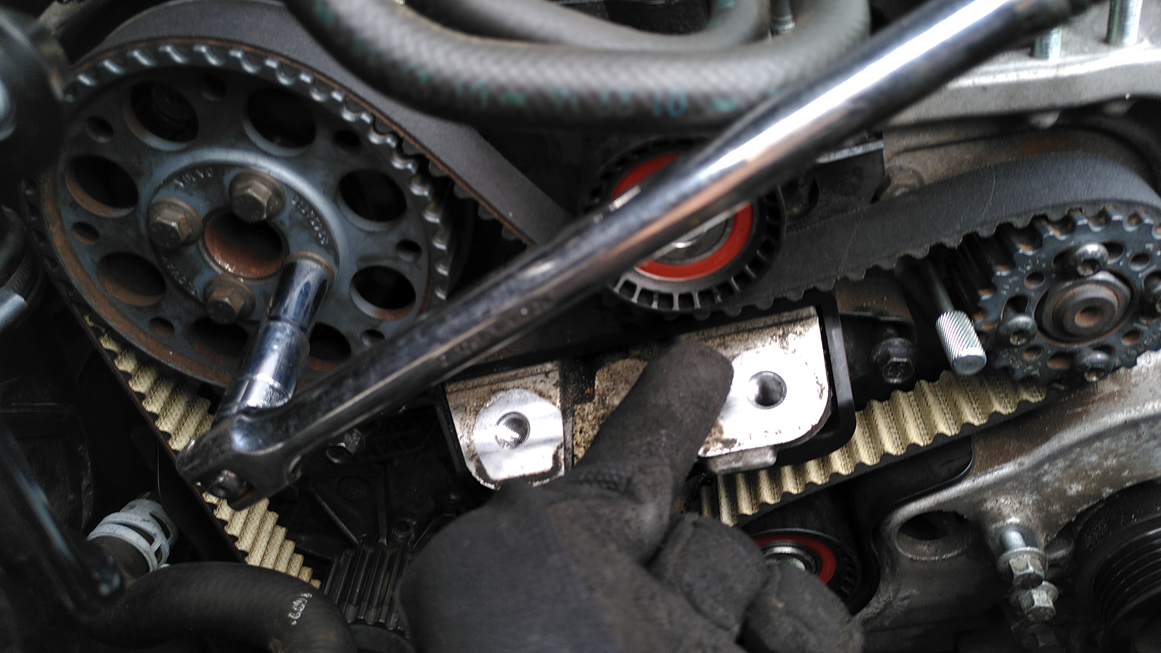
Put a small breakerbar or similar on to one of the bolts on the cam pulley and pull down, and as it turns, the section of belt across the top will slacken and you can easily push it under the centre idler.
Just make sure, as I spent an hour before realising this, that the bottom of the belt is tightly looped around the crankshaft pulley and not hanging down below the pulley. You won’t ever get it on if that is the case.
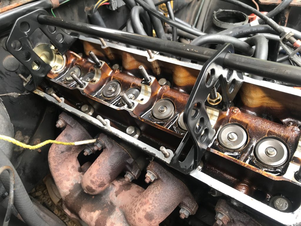
After 250 000 miles, I finally got around to renewing the valvetrain components of my Volvo 240. Springs and hushers being the main items to replace. I also adjusted the fuel distributor system pressure, control pressure, flow plate and CO mixture.
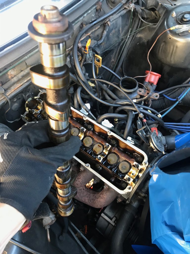
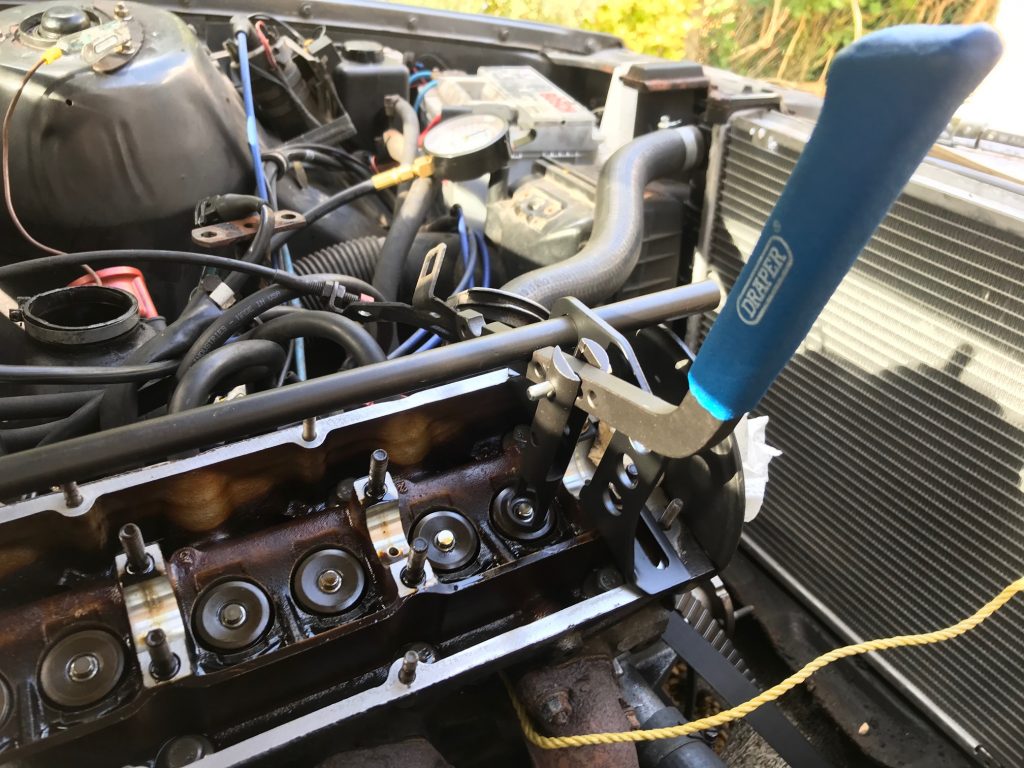
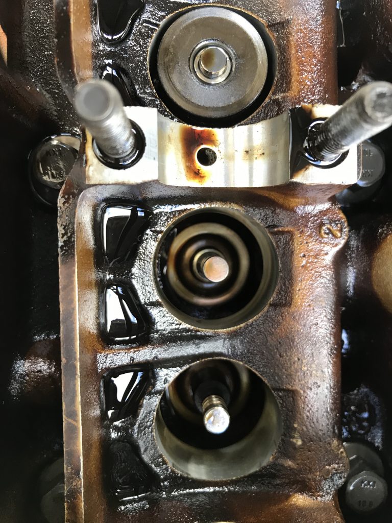
All back in!
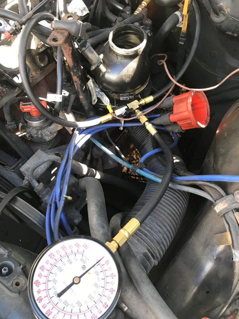
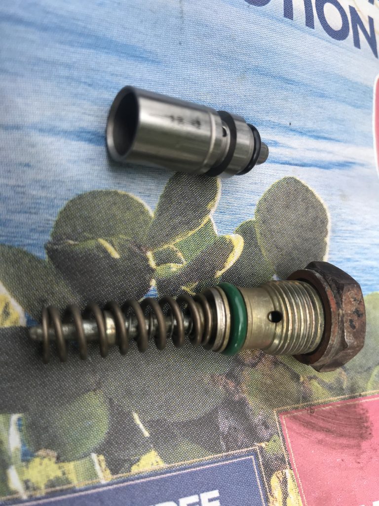
System pressure was only 4.6 (not shown in photo), so I carefully got the pressure regulator out and added shims to it. Quite a lot of shims was needed, I think the spring had gone weak.
That’s it. Next, replacing the power steering pump…
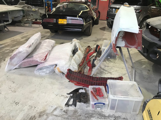
Here she is, looking sad, left behind with a pile of parts…